Practical advice
- Pull the plug out of the socket before carrying out any work on the power tool.
- Do not operate your power tool without the auxiliary handle (2).
- Only apply the power tool to the screw/nut when the tool is switched off. Rotating tool inserts can slip off.
The torque depends on the impact duration. The maximum achieved torque results from the sum of all individual torques achieved through impact. Maximum torque is achieved after an impact duration of 6–10 seconds. After this duration, the tightening torque is increased only minimally.
Instead, the gearbox housing noticeably heats up.
Note: The consequences of excessive heating include increased wear on all parts of the impact mechanism and a high need for lubricant.
The impact duration is to be determined for each required tightening torque. The actually achieved tightening torque is always to be checked with a torque wrench.
Screw applications with hard, spring-loaded or soft joints
When the achieved torques in an impact series are measured during a test and transferred into a diagram, the result is the curve of a torque characteristic. The height of the curve corresponds with the maximum reachable torque, and the steepness indicates the duration in which this is achieved.
A torque gradient depends on the following factors:
- Strength properties of the screws/nuts
- Type of backing (washer, disc spring, seal)
- Strength properties of the material being screwed/bolted together
- Lubrication conditions at the screw/bolt connection
The following application cases result accordingly:
- A hard joint is a metal-to-metal screw application which uses washers. After a relatively short impact duration, the maximum torque is reached (steep characteristic curve). Unnecessary long impact duration only causes damage to the machine.
- A spring-loaded joint is also a metal-to-metal screw application but uses spring washers, disc springs, studs or screws/nuts with conical joints. It is also called a spring-loaded joint when extensions are used.
- A soft joint is a screw application of e.g. metal on wood or a screw application that uses lead washers or fibre washers as backing.
For a spring-loaded joint as well as for a soft joint, the maximum tightening torque is lower than for a hard joint. Also, a clearly longer impact duration is required.
Determining the impact duration
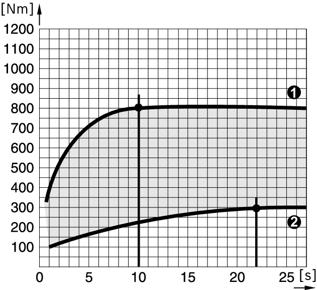
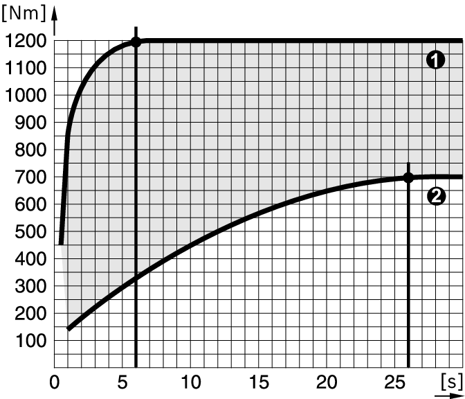
The diagrams (examples) show the tightening torque [Nm] depending on the impact duration [s]:
❶ for hard seat
❷ for soft seat.
The values provided are average values and differ depending on the application. As a control measure, always check the tightening torque with a torque wrench.
Diagram for GDS 24

The maximum torque is achieved:
- After an impact duration of approx. 10 seconds for a hard seat
- After an impact duration of approx. 22 seconds for a soft seat
Diagram for GDS 30

The maximum torque is achieved:
- After an impact duration of approx. 6 seconds for a hard seat
- After an impact duration of approx. 26 seconds for a soft seat
Guide values for maximum screw/bolt tightening torques of commercially available screws/bolts can be found in the following table.
Guide values for maximum screw tightening torques
Figures given in Nm; calculated from the tensional cross-section; utilisation of the yield point: 90% (with friction coefficient µtotal = 0.12). As a control measure, always check the tightening torque with a torque wrench.
Property classes according to DIN 267 | Standard screws/bolts | High-strength bolts | |||||||||
|---|---|---|---|---|---|---|---|---|---|---|---|
3.6 | 4.6 | 5.6 | 4.8 | 6.6 | 5.8 | 6.8 | 6.9 | 8.8 | 10.9 | 12.9 | |
M8 | 6.57 | 8.7 | 11 | 11.6 | 13.1 | 14.6 | 17.5 | 19.7 | 23 | 33 | 39 |
M10 | 13 | 17.5 | 22 | 23 | 26 | 29 | 35 | 39 | 47 | 65 | 78 |
M12 | 22.6 | 30 | 37.6 | 40 | 45 | 50 | 60 | 67 | 80 | 113 | 135 |
M14 | 36 | 48 | 60 | 65 | 72 | 79 | 95 | 107 | 130 | 180 | 215 |
M16 | 55 | 73 | 92 | 98 | 110 | 122 | 147 | 165 | 196 | 275 | 330 |
M18 | 75 | 101 | 126 | 135 | 151 | 168 | 202 | 227 | 270 | 380 | 450 |
M20 | 107 | 143 | 178 | 190 | 214 | 238 | 286 | 320 | 385 | 540 | 635 |
M22 | 145 | 190 | 240 | 255 | 290 | 320 | 385 | 430 | 510 | 715 | 855 |
M24 | 185 | 245 | 310 | 325 | 370 | 410 | 490 | 455 | 650 | 910 | 1100 |
M27 | 275 | 365 | 455 | 480 | 445 | 605 | 725 | 815 | 960 | 1345 | 1615 |
M30 | 370 | 495 | 615 | 650 | 740 | 820 | 990 | 1100 | 1300 | 1830 | 2200 |
Example for determining the impact duration (GDS 30)
Bolt M 24 with property class 8.8 = bolt tightening torque of 650 Nm
From the diagram for GDS 30, 650 Nm results in an impact duration of 0.8 seconds see .
Tips
Torsion bars have a shank with a precisely calibrated, reduced diameter. This means that they limit the torque. A torsion bar is slotted between the impact driver and the bit.
As a rule of thumb for application, the following applies: Core diameter of the screw = effective diameter of the torsion bar. The impact duration is to be determined through test screw applications.
A suspension eye (1) is attached to the power tool's centre of gravity so it can be hung up.
You can use an elbow (accessory) to change the position of the handle.
At sub-zero temperatures, the power tool should first be operated at no load for approx. three minutes to improve the lubrication performance in the power tool.